![]() ENIGMA
ENIGMA
![]()
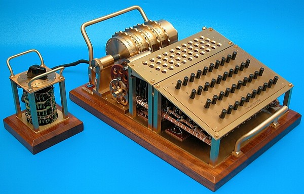
ENIGMA and its variants is a German electromechanical machine for message encryption whose use was widespread during the WW2.
It symbolizes the victory of the Allied code breakers, which can be estimated that their efforts have shortened the war by at least one year.
Many sites evoke the history and operation of this machine and we invite the visitor to also read these 92 pages PDF FILE made by students and well documented.
Unless you have deep pockets (more than 100 000 $) and lot of luck, the acquisition of a real old machine is a real utopia.
To revive this machine, there is no more than five solutions :
- Building it ! See still works on http://www.tatjavanvark.nl/index.html#works, it's absolutely amazing.
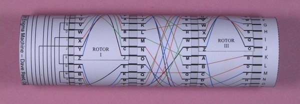
- One sheet of paper (yes it works) with data given on the
website:
http://dave-reed.com/DIYenigma/index.html
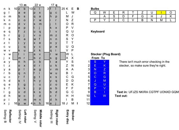
- Run a simulation on PC :
http://cryptocellar.org/simula/
or http://users.telenet.be/d.rijmenants/en/enigmasim.htm
and even an Excel spreadsheet :
http://chrisrae.com/programming/index.html
Or...
- Build a replica :
This kit is for sale on the Internet for € 130.00 excluding postage : http://www.cryptomuseum.com/kits
In the box are :
- A double-sided epoxy professional with metallized holes and silk screened.
- All necessary components with the programmed PIC microcontroller.
- Two-sided A3 sheets giving schematics and components locations.
- A 68 pages very comprehensive manual (in English). It includes step-by-step assembly of the circuit in the Heathkit style, for those who know. All is described step by step. There is also the description of a wooden box.
An entire chapter is devoted with great detail to the operation of the mechanical machine and its history. There are even examples of messages to decode !
In short, a remarkable work within reach of a neophyte but knowing handle a soldering iron and wire cutters.
The installation works from the last solder performed. It only remains to put in wooden boxe and possibly add some accessories.
This will be the subject of the following descriptions.
You have for download HERE a file containing all plans and current patterns.
POWER SUPPLY
The kit is designed to be powered by an AC adapter 8-12 V (not supplied) or batteries of 8-16 V (a 9 V batterie make also a good job but only for 6 hours !).
We chose to put the AA Ni-MH batteries inside the box and recharged by a small electronic assembly. The power socket (AC or DC) was placed on the right side of the Steckerbrett plate. Below, a red LED "Low Battery"indicator flashes to indicate when it's necessary to recharge the batteries.
An ON-OFF sub-miniature switch has been placed in the center of Steckerbrett in an unused mounting hole.
MORSE LISTENING
The mechanical Enigma machine does not directly produce a Morse code. Around the machine, there are two operators. The first simply type the letters of the message to be encoded one by one each time until the second operator has carefully noted the letter from the coding. This second message is then transmitted by a Morse operator.
In the electronic version, this step is integrated into the machine and you can hear the letters handled in Morse provided to add a buzzer or a low-frequency oscillator. One might even consider directly send the signal to a transceiver but it's strictly prohibited by law in some countries (encryption). Note that an RS232 output for connecting a PC in terminal mode or to connect two machines.
The RS232 socket has been placed to the left on the Steckerbrett and below, the green LED of the microcontroller was deported from its original location.
MECHANICAL ASSEMBLY
In our project, we have (unfortunately !) hid a lot of electronics.
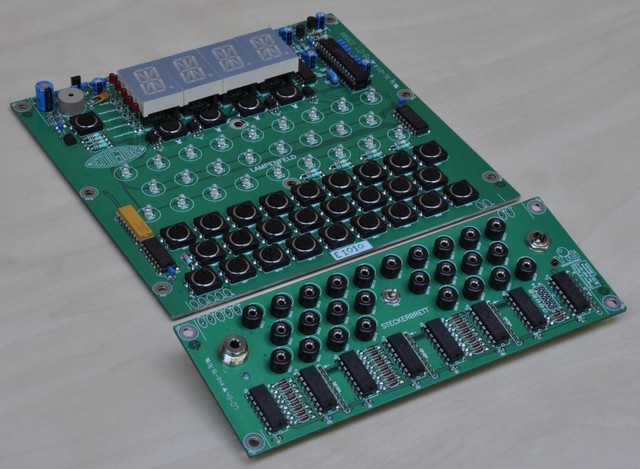
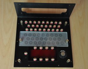
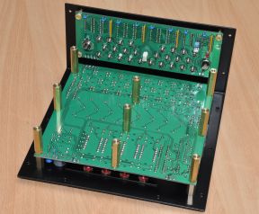
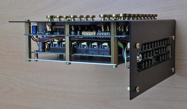
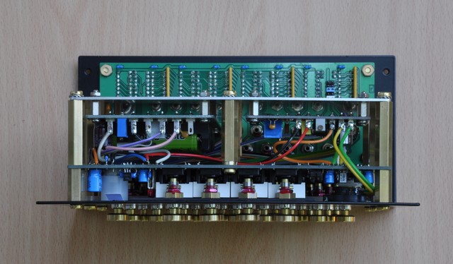
Compared to the original installation, the display is raised to 6 or 7 mm with IC socket to put them at the same height as the cover letters that will help cover the whole by an horizontal plate (17 mm from the circuit). Similarly, on the Steckerbret the components exceeding the height of integrated circuits (resistor network and decoupling capacitors) are soldered on the printed circuit back face.
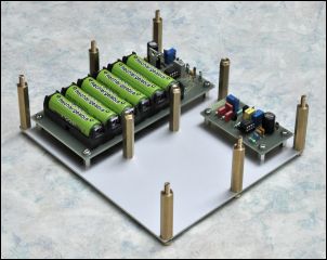
A plate attached below the PCB by spacers supports batteries and Morse signal generator.
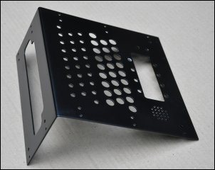
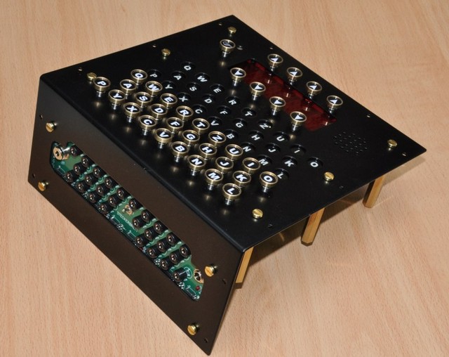
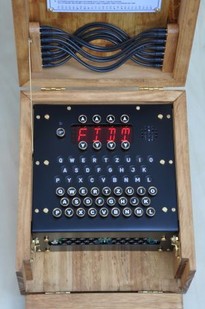
The chassis is perforated over the yellow LEDs Lampenfeld so as to illuminate the letters on their entire surface. As in the original, the letters are white on black (ink jet printing on a transparency or using mylar now supplied with the kit). A sheet of frosted plastic, also supplied, is placed against the mylar for uniform brightness across the letters.
Over the display a red filter enhances contrast.
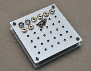
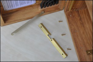
The keys are a little mechanical problem. To keep things simple and make maximum use of standard products, we plan to use banana sockets and 4 mm outside diameter brass tube (3 mm inside) sold in lengths of 1 m at the DIY store ( In France : Leroy, Castorama, Briconautes, etc..). The banana sockets are eventually enlarged to 4.1 mm if the tube does not slide well and the base is incised with a fine tooth saw mill of 1.6 mm. This allows, with a piece of 1.5 mm brass piano wire set in the bottom of the tube, to provide anti-rotation key.
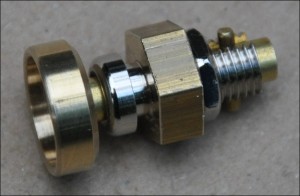
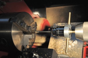
The hollow disk receiving the wafer is machined in a 12 mm brass rod, with an end mill of diam. 10 mm and a center hole of 4,1 mm.
The wafer are obtained with a cutter "homemade" adapted to the inner dimension of the keys :
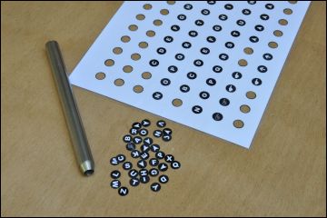
We also
conducted a "pasting table" for holding the keys on their axel at the
correct height during the hardening of Araldite glue. The letters are pasted on the final
assembly when completed, this to compensate for angular errors and to have
perfectly straight letters.
.... And is wired, tested, yet to make a wooden box.
FINAL ASSEMBLY
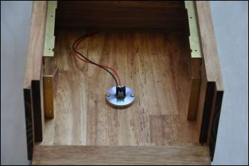
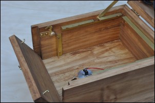
The wooden box was made of pine and varnished. In the bottom, we placed a miniature switch connected to the strap of the No. 2 jumper's dual row header. This lets you choose the operation with the Morse generation or RS232 output which will be discussed later.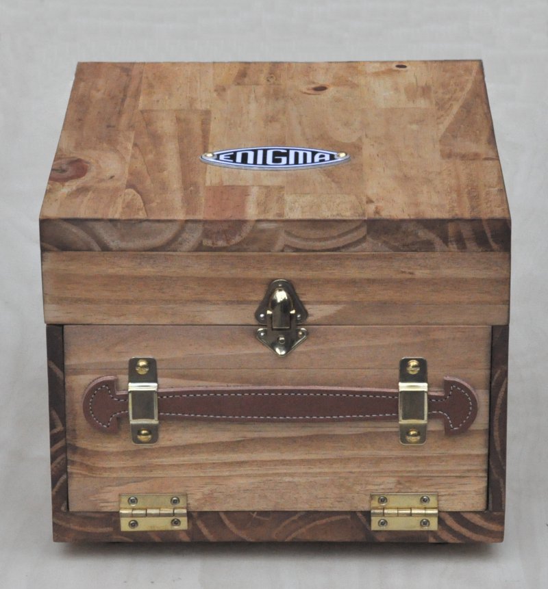
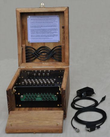
In the
cover, twelve cords are provided for the possible links between the sockets of
Steckerbrett.
RS232 LINK
The serial link allows you to display on a computer terminal encoded characters or to connect two machines.The easiest way is to use HyperTerminal in Windows located at : All Programs / Accessories / Communications / HyperTerminal.
But there are other programs like RealTerm, TeraTerm, Termite, more or less sophisticated.
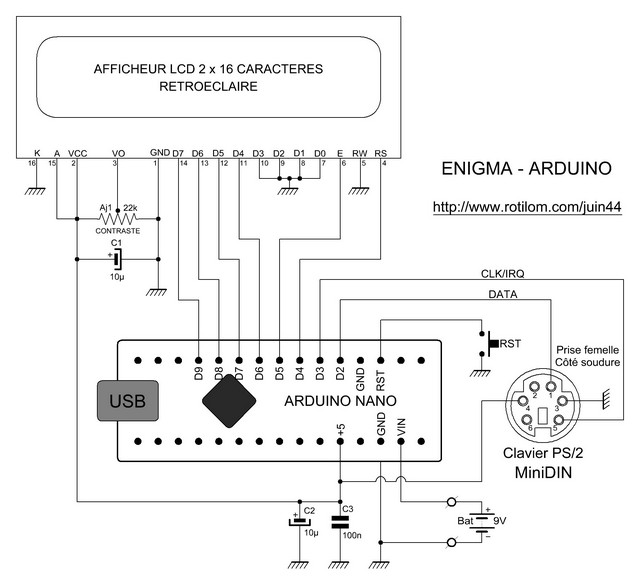
ENIGMA - ARDUINO
Even simpler but perfectly working, an Enigma with a single integrated circuit, a 2-line LCD display and a computer keyboard.
It is a circuit found on the Net that we tested and adopted. Cost price, less than 10 euros!
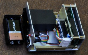
Compared to the original description, we used an Arduino Nano that we attached to the back of the display. A 6-pin Mini DIN connector connects a computer PS2 keyboard. When using a USB keyboard, it is necessary to use an adapter that is easily found on eBay.
To make the unit totally self-contained, it is powered by a 9-volt battery placed in a drawer holder. The use is not daily and with a low consumption (50 mA), the battery can last for a long time and can be used in other devices.
The program must be slightly modified to adapt it to the pinout of the LCD. On the author's site you will find the original sketch and the instructions for use: http://apcmag.com/arduino-projects-enigma-cipher-machine.htm
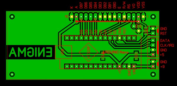
Components side of the PCB (don't forget the wire between VDD and A)
Procedure for encrypting and decrypting
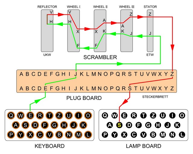
A very simplified diagram, the round trip circuits are double and the wheels connections do not represent the reality.
First of all it will be necessary to obtain the Code Book necessary to initialize the machine. Each page corresponds to a month and thus has 29, 30 or 31 lines. More prosaically we will use a program that allows to generate it month by month. This program can be found at:
http://users.telenet.be/d.rijmenants/en/codebook.htm
We will encrypt a message corresponding to the code of the 29th of this month. In line Tag 29 we have the initial parameters of the machine.
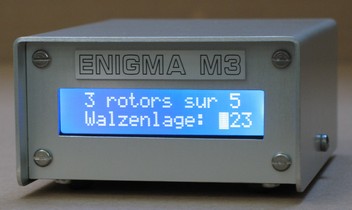
For simplicity, the machine is an Enigma with 3 rotors out of the 5 available and reflector B (UKW B).
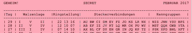
Tag is the day of the month.
Walzenlage is the selection and order of the rotors in the machine, from left to right.
Ringstellung is the position of the rotor wiring, relative to the alphabet ring of each rotor. Here we have figures which correspond to the order of the letters of the alphabet: 22 is the letter V, 13 the letter M and 16 the letter P. The first Heeres Enigma (Wehrmacht and Luftwaffe) contained figures on the periphery of Rotors which was no longer the case with the M3 Naval Enigma (Kriegsmarine). A correspondence table appeared in the cover.
Steckerverbidungen indicates the position of the cables connecting the plugs on the plug board (Steckerbrett). In our example, the plug A is connected to the plug U, the B to the W, and so on. Here are the ten wires out of the thirteen possible. Having extra cables does not increase the encryption strength.
Kenngruppen are
the identification groups.
The operator begins by selecting one of the four three-letter identification groups by adding two random letters at the beginning of the group (Buchstabenkenngruppe). For example, if one chooses the third group YSU one could have ENYSU, BZYSU, XWYSU, etc.
In our simulation we will take the VZYSU group. This group will be placed at the beginning of the message but it will not be part of it and therefore will not be encrypted.
After having indexed each wheel according to the "Ringstellung" and placing them in the correct order in the machine, the operator places the wires in the sockets corresponding to the "Steckerverbindungen".
Then he chooses a random starting position of the rotors (Grundstellung) and a key (Spruchschlussel).
For example GZF and HSE.
It then rotates the rotors so as to display GZF and hits the HSE keyboard which successively lights the OFO letters. This is the encrypted key. GZF and OFO will be in the message header.
The operator, after placing the rotors again in the HSE position, types the message into five-letter groups and various conventions are used to transmit the digits, punctuations and abbreviations. For example, the point or space between words is replaced by an X and the digits are in plain letters.
The operator's assistant notes the letters from the encryption, one after the other on a special sheet called Spruch, a contraction of Funkspruch (radio telegram), which contains blocks of five columns. The header is also indicated with the name of the sender, the recipient, the time, the total number of letters, the starting position and the encrypted key.
This sheet will be given to the radio operator responsible for transmitting the morse message on the radio waves.
Here is our test message with below the letters translated by the machine and visualized by the lighting of the lamps:
CEXTE XTEXA XETEX CODEX AVECX
UNEXE NIGMA XMXTR
OISXN AVALX
WIEVP QUDWX
IGLRD SUOQE NBQJJ
BUZGO QUWRY JTTIG CMHTI
PMRRV
We now have the "Funkspruch" that the recipient will have to decipher
YOU DE ME = 55 = GZF OFO =
VZYSU
WIEVP QUDWX IGLRD SUOQE
NBQJJ
BUZGO QUWRY JTTIG CMHTI
PMRRV
It will then set up the machine according to the data of 29 and place the rotors in position GZF. It then types the OFO encrypted key and gets the key HSE for the message. These three letters indicate the initial position of the rotors to decrypt the message. The decryption begins with the second group of five letters, the first group not being one.
During the typing you cannot go back, so be careful not to make any mistake otherwise the rest of the message is illegible.
![]()